Magnetic Cold Fusion Motor
Magnetic Cold Fusion Motor
Magnetic Cold Fusion Motor
Magnetic Cold Fusion Motor
Magnetic Cold Fusion Motor
Magnetic Cold Fusion Motor
Magnetic Cold Fusion Motor
DRAWINGS:
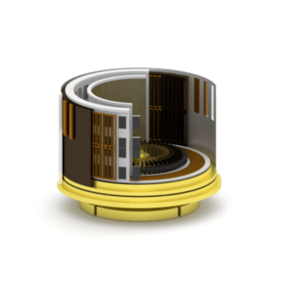
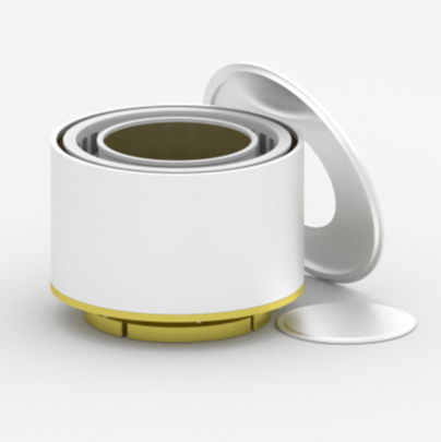
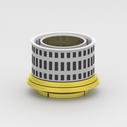
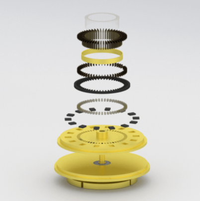
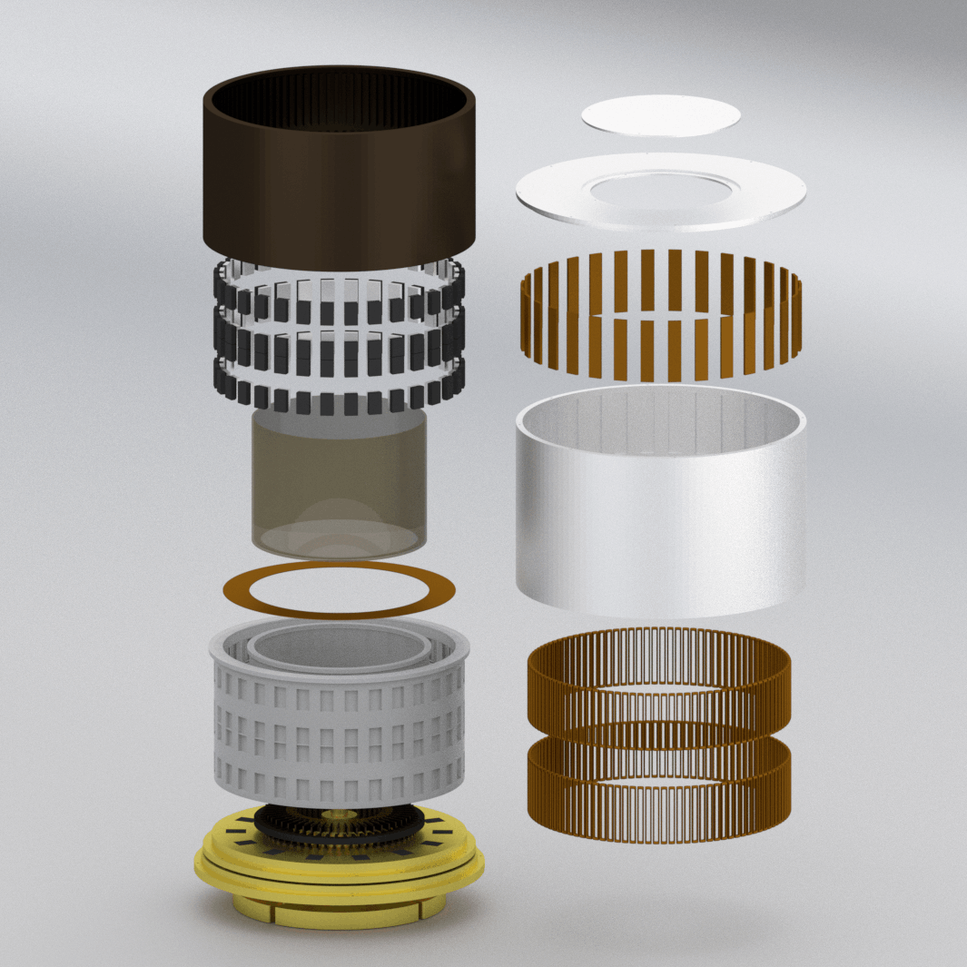
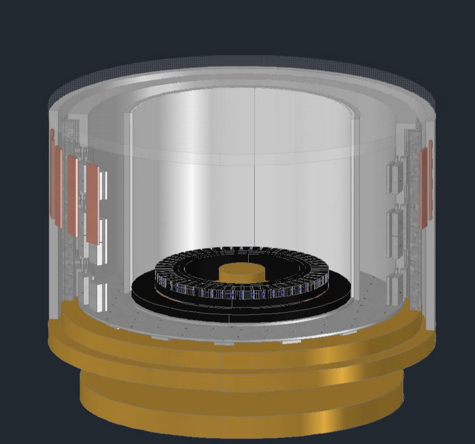
Cold Fusion Motor Drawings (shown above)
Cold Fusion Motor Hand Drawings
Cold Fusion Motor – PDF
- Cold Fusion Motor harnesses free energy from the environment
- Cold Fusion Motor works with a form of magnetic energy that is clean and renewable
- Cold Fusion Motor produces magnetic equivalent of 12 H.P.
- Cold Fusion Motor is designed to power several Magnetic Oscillating Water Purifiers to convert salt water to fresh water
- Cold Fusion Motor requires mechanical startup
- Cold Fusion Motor requires palladium plates
- Cold Fusion Motor proves that it is the misuse of nuclear energy when radioactivity results
We are providing this free information out of love to help heal our planet. Please help us in educating people about magnetic energy.
This Cold Fusion Motor, like the other units, is an inter-dimensional device, meaning that it establishes neutral magnetic vortices that tap into higher dimensions allowing the unit to function with a seeming surplus of energy. In reality, none of these magnetic devices are over-unity if you consider the contribution of higher dimensional energy…the input always matches the output. Needless to say, fusion without high heat is a gateway technology that will change the world, but it’s not just a tremendous power source. The principles behind this unit will show people how to combine materials in a revolutionary new manner. Imagine seamless clothing, seamless flying cars, seamless buildings – all made with natural, healing materials that flow with energy that is harmonized with the human body. In this new world of material science, molecular bonds are easily unlocked and reconfigured with low temperature pulsing neutral magnetic fields. Materials will be combined and blended in ways that seem impossible by today’s standards, and they will still be natural with higher dimensional energy easily flowing through them.
Several groups of researchers around the globe are exploring the area of cold fusion, and they are producing results that demonstrate the validity of this concept. We are on the threshold of opening a new paradigm of science that will produce pollution-free technology. This power source is dependable and controllable, but we do not recommend it for transportation (unless this unit is modified) because it must remain level to prevent the liquid from spilling.
There is a Universal perspective that could greatly assist people in bringing forth a new scientific paradigm. Empiricism is holding back the development of technology that could heal our ailing planet. Science has resisted the belief of multidimensional energy and omnipresent energy fields that can be easily harnessed. Ironically, science has also resisted the idea of a Creator Force that is omnipresent and unlimited in nature. It is time for people to stop ignoring evidence that contradicts current theories that are leading us into destruction. We must embrace theories and technology that hold promise for our future, that reach beyond the current limitations we have arbitrarily set for ourselves, and we must begin consciously working with the Creator Force that we are one with to create a world that will flourish in love.
Caring for this planet needs to become a higher priority for people. Nuclear pollution, chemical pollution, air pollution, water pollution, ground pollution…all pollution needs to stop. This is our home, relocating is not an option. We must begin to use technology that will recycle energy, conserve our natural resources, and stop polluting the environment. We must stop building conventional power plants and stop abusing our environment for financial gain. We must realize that the use of oil is killing us, and the production of electricity is killing us. Our environment can only take so much abuse before the planetary system must make radical adjustments to maintain a harmonic energy balance. It would be wise for us to begin treating each other and our planet with more love.
This cold fusion unit does not work on conventional nuclear principles. It is a misconception that heat is required to perform fission or fusion. Certainly, high heat can produce nuclear reactions but this process is not natural, nor is it the process stars utilize. Magnetic fields of certain vibratory frequencies allow molecules to be blended without high heat to produce various results including heat, light, and usable energy. Harmful radioactivity is not necessary to perform nuclear reactions. It should go without saying that people should avoid working with chemicals and elements that harm humans, animals, and the environment.
As with the other units we have presented, this unit did not evolve through trial and error, it was produced through a series of revelations. Other cold fusion experiments may not be at this level, but given the condition of our planet, we cannot afford to lose many years to development of a concept that could be critical to our survival. We welcome other researchers to finish their projects with this information.
Natural magnetic energy from the earth’s magnetic field can be used for our benefit and safely recycled, allowing us to harness an unlimited supply of energy. This cold fusion motor is a vivid demonstration of the power of blending certain elements, in certain conditions with flowing magnetic current to produce mechanical power that is useful. This motor is basic model that can be modified to produce various results.
All energy is magnetic molecular structures with some of these structures being magnetized and some not. To explain this motor, certain forms of ‘influencing energy’ can not be ignored, therefore when referring to “all energy” we include what is now called gravity, which is actually compressed magnetism, the catalyst for all energy. Gravity plays a critical role in most technology, including this unit. All magnetic molecular structures are in a constant state of change, forming and reforming with the action always resulting in 100% efficiency. Magnetic structures draw from an unlimited source of energy that is multidimensional in nature. When magnetic structures are in need for restructuring they automatically attract the necessary structures that respond at a nearly infinite velocity. For every molecular structure that is known, there are equal ones being made, offshoots if you will, so that ultimately there are no unknown structures. The offshoots of the molecular structures exist at a higher vibration, but the proper magnet field can lower the vibrations of the offshoots and allow those structures to be utilized for various purposes. This utilization of energy offshoots is precisely how this motor maintains a consistent supply of energy. For every unknown structure combination there is a known structure combination. There are unending varieties, not unlike the vast array of color combinations available within the color spectrum.
Using this background of knowledge, let us now address the cold fusion motor’s mode of operation. The main shaft is first driven at 5700 r.p.m.s, and a 3 volt power source is caused to feed energy into the system. (When applying the voltage do not misconstrue the amperage required.) This action starts a charging process which manifests as magnetic bubbles. It could be stated that the copper screen, part #15, after building a magnetic charge, has this energy move basically in an ‘upward direction’ (as minute bubbles). Simultaneously magnetic waves from the permanent magnets flow through the 96 palladium plates which creates a disturbance factor. The disturbance factor intermingles the molecular structures that are already (recycling of itself) present, fusing them together in a giant mass that ultimately creates the liquid surface tension, which then resolves itself by recycling.
We see therefore the basic mechanical design of this motor is to incorporate a system of hardware to capture magnetic energy during it’s recycling transfer movement and thereby continuously produce 12 H.P. of energy. The capture of this free energy is achieved at the surface of the liquid through use of a certain ‘polarity charge’ that is manifest within and on the top row of 32 palladium plates. Palladium is used because it stimulates and motivates energy movement after being contacted. The contact to these plates ‘must be at’ only the very bottom surface. The unbroken bubbles are drawn to the magnets through the palladium to itself. Thus we see the bubbles are captured just before they break. It is important to note that the bubbles being drawn through the palladium are compatible with the magnets. The composition of the magnets is critical.
The liquid level needs to be exactly maintained. The key to correctly capturing this ‘bubble’ magnetic energy is to capture it ‘while in the bubble state’. The liquid level or height of the surface tension is one important feature for this correct ‘flow capture’. A second action almost of equal importance is to offer this surface tension magnetic energy the proper field to go into, a field having a particular polarity. How does this unit produce this desired polarity? The method used is to drive, at start-up, a generator winding made of insulated copper coils ‘in front of’ permanent magnets. These coils are connected as closed loop windings that have each start wire connected to its compatible finish wire. As the north and south magnetic faces bombard these closed loop coils the magnets appear to cancel each other. However, what is created is a usable, neutral energy. This neutral magnetic energy flow is the ‘offered polarity’ that is compatible to the ‘bubble energy’. As this ‘captured’ energy then joins the flow system of the permanent magnets, these magnets respond as very powerful force fields.
This explanation allows our thinking to expand and entertain vast possibilities of the neutral magnetic molecular structures blending into LIKE ACCEPTANCE thus eliminating the idea that an attract field is required.
The following explanation of the parts will be given ‘proper attention’ as we continue to address this subject of magnetism. One must observe and take note that the pulses which drive the motor are achieved by the magnets as they interact in two different directions in a simultaneous manner. This pulsing happens as a result of the fact that a magnetic flow (as opposed to electrical) is doubled in speed.
To accommodate this magnetic flow activity, jumper wires are secured to the motor commutator that actually cause a double turn of commutation. These jumper wires allow a ‘flow balance’ to happen. For example, the connection pattern shows the motor has a 1,2,3 pattern of flow, however, each group of coils’ does not build up an exact charge from the passing of the magnet faces. The magnetic energy in the bubbles flows to the surface randomly thus some groups of coils charge-up more than others. The jumper wires (and the graphite ring) allow this energy to be distributed in a pattern as needed to the motor coils that are ‘ready for’ a new energy charge.
To simplify the matter, the magnetic pulse sequence is being identified as if there were only one kind of magnetic energy involved. With a greater desire to learn how this motor functions, further investigation will reveal that there are differing kinds of magnetic charge. The copper bars (as stated in the theory of copper revulsion) establish an opposition to the polarity herein. The generating coils, as their pulse charge exits, set up a magnetic response that, in turn, contributes to rotation. As this charge ‘crosses over’ to the graphite ring #17, it causes the motor commutator to attract the ‘graphite charge’, which adds to the speed control and horsepower.
When the motor coils ‘pull toward’ the permanent magnets and are momentarily shut-off, this magnetic energy flow then instantaneously joins the generating flow, recycling a stabilized magnetic energy. Therefore, the concept that is connected to the word ‘magnetism’ is inadequate to describe the total variety of like and compatible energies which have been left, to date, unidentified.
One final item needing to be addressed, before the actual commutator circuit is explained, is that if only ‘electrical flow knowledge’ is applied to check out this circuit then a problem of understanding will result. For example, the two commutators (generator and motor) only pass very ‘close to’ the graphite ring #17 and their travel path then shows what in electrical terms would be called an ‘open circuit’ or ‘shut down’. It is important to know that when focusing on the ‘magnetic circuit’ inside this motor, cut-off time does not mean a shut down of the magnetic power driving this motor. The set-up poles maintain their strength to a needed degree without a continuous flow crossing over from the graphite ring to the motor commutator.
HOUSING CONSTRUCTION
It now becomes important to focus on the statements made about energy in order to avoid making serious mistakes during motor construction. The desire is to have a motor produce 12 horsepower for an indefinite amount of run time without any loss of power. The materials used for construction have a direct bearing on ‘how long’ the energy production will remain constant.
The permanent magnets have a draw factor to the atmosphere and draw the needed magnetized magnetic molecular structures to remain constant in energy. Thus the magnets must remain in correct relationship to the atmosphere which then allows this draw factor to take place unobstructed. Other than the steel laminated armature frame #5, there are no metals used that could cause the magnets to expand their field. For example, if the outer housing were made of iron, as is common in electric motors, then a magnetic short circuit would happen and this negative event would quickly manifest as a problem of energy dissipation.
EXPLANATION OF FIGURE ONE DRAWING
This full size side view shows the relationship between the motor/generator windings and the permanent magnets as well as the palladium plates. The following parts list explains how to construct this unit. However, we wish to draw a strong focus, at this time, on very important magnetic activity that ‘helps to’ create the ‘disturbance factor’ which results in structures fusing together in a giant mass that ultimately creates the needed surface tension.
Notice the point where the two center permanent magnets are 1/32 of an inch apart. A very powerful magnetic activity takes place because of this 1/32 inch spacing. The tank thickness of 1/16 inch is the distance that the 40 thousandths thick steel wire is away from the magnets. The steel wire is copper coated. This wire forms a ring 13-9/16 inches in diameter. All along this ring a total of 64 powerful permanent magnets are attracted to the inner steel core of this wire. The copper coating is not influenced by this same ‘attract condition’.
Next, we focus on the action of the 3.5 volts Direct Current being fed into this wire and for the most part the copper coating is the flow path which circuits this voltage. We see therefore, for the magnetic attract to ‘get to’ the steel core, it must cross through the copper coating which is flowing the 3 volts D.C. This copper coating makes firm contact to the palladium plate on the side facing the permanent magnets. Copper, in this instance, serves somewhat like a magnetic insulator and must not be scratched, exposing the steel core. The palladium plate responds to this magnetic action by allowing a magnetic flow to pass through this plate en route to attracting the plus wire which is firmly mounted to the opposite face. The ‘core’ of this ‘plus’ wire, being steel, attracts the magnetic flow through the palladium.
Now as we focus on the plus wire, we find that it is actually completing a magnetic attract circuit of opposite polarity to the bottom palladium plates, which have permanent magnets penetrating these plates, thus causing an attract field to pass through them. This intense magnetic interaction is happening while submerged in the hydrogen peroxide. As the motor coils get ‘charged up’ by the graphite ring this energy ‘crosses over to’ either north or south permanent magnets because it is neutral energy. Thus an alternating current flow, caused by rising and falling coil charges, constantly bombard the ‘structures’ which are inside the liquid, To grasp the full excitement of this wonderful circuitry demands very close attention to detail.
PARTS LIST
lA,B,C) Brass base, brass center shaft and non-magnetic ball bearings. Brass is ideal in that it does not expand the magnetic field. The 12 H.P. of energy is removed for use through this shaft which is located at the bottom of the unit. This shaft is also used for start-up ‘spin charging’ of the unit.
2) Outer wall made of aluminum because it allows the motor to build a certain magnetic circuit that ‘enhances’ the draw factor to the atmosphere for the permanent magnets.
3) Copper bars bonded to outer aluminum wall, 1/8 inch clearance from steel core. Their relationship to the magnets is aligned to the spacing between the magnets. These copper bars are located at the upper motor winding area. The ‘polarities’ of these magnets are arranged to pull to the magnetic coils. These copper bars respond by manifesting as a ‘push’ or opposing field.
4) Brass support plate rotates the parts shown without expanding or ‘interfering with’ the magnetic flow of the unit.
5) Ring of laminated steel assembled by using standard motor laminations with each lamination measuring 25 thousandths thick. Before winding, this part should first be firmly bolted to part #4 and balanced at 5700 r.p.m. Next, this welded laminated core could be removed and coils inserted. (Row weld, as needed, on the back side only.) The space opening for inserting the coils should be minimal.
6) Motor winding inserted at top core winding location with coil wires having a thin tubing cover. Next, these wires are circuited through the generator slots, directly to the motor commutator (using holes in part #4 as needed). The insulation between groups of coils and the slot liner need be minimal because high voltage is not produced as this unit operates. The generator slots could be used as a circuit passageway because the 144 turns of #26 copper motor wire in each slot will ‘easily fit’, thus allowing room for these motor coil wires to ‘pass through’.
7) The generator winding is wound with the identical coil turns and groups. However, as each group of two coils is inserted into the slots, the wires should be left long enough to be circuited ‘directly to’ the generator commutator. As these wires travel to the commutator they are to be gently twisted together (with the plastic coat varnish insulation not removed) and an insulation tube slid over both twisted wires. The generated magnetic energy travels across from wire to wire as the energy advances, thus keeping these two wires in ‘close tight proximity’ allows for the best energy transfer.
8) Partial cover plate allows quick access to the center of the motor. This ‘open area’ inside the motor is used as a liquid storage area with the storage tank supported from the underside of the center cover. As time passes, this tank will need to be removed for refilling, thus a partial cover plate allows for quick, easy maintenance. NOTE: The liquid does not need to be changed or replaced, as for example, changing your oil. The liquid gets used but does not have its properties destroyed.
Explanation of Part 8. By saying the liquid gets used but does not have its properties destroyed, we mean that the properties were used in a transmuted form – hydrogen peroxide and water into energy, which is their basic property anyway, (the peroxide being the catalyst for the hydrogen). Nothing exists outside of energy; it is the basis of all life and all matter. So although the level lowers it isn’t that it’s been dissipated, merely transformed into another use. You simply add to continue the transforming or transmuting, if you will.
9) Tank made of aluminum (if cost is a factor). Ideally, this tank could be made of injection molded material having no metal, thus eliminating the need to insulate the palladium plates. Do not change the liquid volume of the tank because this volume has been adjusted to produce the required magnetic surface tension, which is the exact amount needed to feed a 12 H.P. unit.
10) Tank liquid, a blend of two/thirds Hydrogen Peroxide (3% solution) to one-third distilled water. Liquid is readily available through any pharmaceutical supply company. Deuterium is not used as it is of paramount importance that the bubbles be captured ‘before they break’ and deuterium is TOO HEAVY. The Hydrogen peroxide produces very light bubbles, and because of the vacuum inside the unit these light bubbles maintain their strength and ‘transport’ the energy as needed to the place where capture takes place. Think of this liquid as a conduit which transports the magnetic energy.
11) Magnets are new powerful iron/boron/neodymium, mounted with a 1/8 inch clearance from the steel armature, part #5. There are two sizes. The top and bottom rows are 1-1/4 inches high by 3/4 inch wide by 1/4 inch thick, totaling 64 pieces. The two center row magnets are 1 inch high by 3/4 inch wide by 1/4 inch thick for a total of 64 magnets. The generator/motor has a total 128 magnets. Enclosed is a drawing showing the magnets’ polarity placement. A very intense magnetic activity happens as the center magnets are mounted 1/32 inch apart. For safety reasons, after the magnets are bonded to the outer surface of Tank #9, it would be wisdom to use armature bonding tape (non-metal tape) about 1 inch wide. Wrap this tape around the exposed face of these magnets for a thickness of 1/32 inch.
12) Two sizes of palladium plates. The top and bottom plates measure 1-1/4 inches high, 3/4 inch wide and 1/8 inch thick, totaling 64. The center row of 32 palladium plates measure 2 inches high, 3/4 inch wide and 1/8 inch thick. All 96 plates are held to the tank by their ‘side edges’ only, with mylar insulation between. The inner face of all these plates has a 1/16 inch space clearance from the tank wall. This space gives access for the liquid to fill in the middle and bottom rows. The top row has the liquid level only covering the very bottom of each plates which necessitates a level mounted motor. A measurement then, from the face of the permanent magnets to the face of the palladium plates is 1/8 inch. This 1/8 inch is comprised of 1/16 inch tank thickness and 1/16 inch space for liquid.
13A,B) Represent the wire circuit explained previously. The wires must not exit the tank enroute to the D.C. 3 volt power source by being circuited through the liquid surface line. This circuit placement, understandably would be simpler, however, a certain energy disturbance would result causing a break in the surface tension. For this reason, the drawing shows the wires exiting the tank at the tank’s inner vertical surface.
14) Permanent magnets measuring 1-1/8 inches long, 7/8 inch wide and 1/4 inch thick, bonded directly into machined holes located in Part #4. They are positioned as alternating polarities to influence the copper screen located inside the bottom of tank #9. These magnets are also iron/boron/neodymium.
15) A 40 thousandths thick copper screen of close weave. This screen covers the bottom of tank #9 and measures 10-1/4 inches inside diameter and 13-1/4 inches outside diameter. As magnetic energy waves ‘bombard’ this copper screen from the 14 permanent magnets, this energy starts to migrate away from the screen, going ‘basically’ in an upward direction.
16) A 1/8 inch thick coating of mica insulation secured to the tank as shown. Energy that is captured within the tank would dissipate into the motor interior if this inner surface were not properly insulated.
17) Ring of dense graphite held by the tank but insulated from it. This ring is held ‘so as to’ allow the commutators to pass above and below it, as close as possible. This ring of graphite not only serves to ‘store and discharge’ the generator coils’ energy, but also serves as a ‘modulating’ filter sponge that slows down the energy going into it and then accumulates and discharges the energy with ‘controlled pulse charges’. Without the use of this ‘transfer material’ air ‘structures’ would attempt to join the magnetic pulse stream and cause an uneven flow of energy. Therefore, we could say it screens out air ‘structures’.
18) Top commutator for the motor winding needs to be made a ‘special way’. Enclosed is an isometric drawing that shows how mica is not to be between the bars, at the location above the graphite ring part #17, because as the graphite energy charge transfers over to the motor commutator, an attract pulling happens that utilizes this ‘space between bars’ as a pull zone. Ideally these bars should pass ‘as close as possible’ to the graphite without actual contact. Of primary importance is the need to align bar #1 to slot #1 as these parts are secured to brass rotor #4. Figure 2 highlights this placement with a red center line. The group of motor coils in slots #1 and #4, also in #2 and #5 are to be connected to motor commutator bars #50 and #52. This is a vital connection circuit and must be accomplished exactly as shown.
19) 51 jumper wires secured to motor commutator on a 1 to 4 span as shown. Also shown are the jumper wires formed by taking two #26 insulated copper wires and tightly twisting them together, making the needed loop for soldering to the commutator. As stated previously, magnetic energy ‘advances’ by jumping from side to side, somewhat like a tight spaced W pattern, thus jumper wires are formed to accommodate magnetic travel needs.
20) Brass support tube serves as a container to secure the motor commutator. For simplicity this tube could be welded to rotor #4.
21) Mica insulation to insulate commutator from rotor #4.
22) Generator commutator shown in Figure 2, ‘not being aligned’ to the motor commutator bars. The placement as shown is important because the energy is circuited to ‘go first’ in the direction of rotation, thus the generator winding group in slots 1 and 4, and slots 2 and 5, get their start and finish wires connected together, then get circuited ahead of the #1 motor commutator bar, (as shown).
Using this circuit pattern all the generating coils energy gets transferred to the graphite ring where a ‘graphite charge’ makes the connection flow to the motor commutator. The generator bars protrude 1/8 inch past the mica (that is between them) which allows for the needed ‘pulse transfer space. Again, the generator commutator should come as close as possible to the graphite ring without actual contact.
23) Mica insulation to commutator from rotor #4.
24) Holes pre-drilled into part #4 to allow insulation tubing and wires to be circuited to the commutators. For long run time, these holes (after circuit is complete) should be filled with insulating wax to prevent breakage from static vibration. Also the windings should be encapsulated as needed for this same reason.
25) This number represents the Center Cover Plate, all motor joints, including the shaft, which need to be sealed to hold a vacuum.
26) D.C. power source to supply needed 3.5 volts to the palladium plates.
27) Liquid add assembly includes reserve tank inside center portion of this motor (tank not shown) and sensing switches to register liquid level. This liquid level must be controlled within 1/8 inch to prevent loss of power. The bottom of the top row of palladium plates must not be totally out of liquid at any time, otherwise the flow circuit is broken.
This concludes the parts list/explanation.
It appears as if the major factor which will open the door to this ‘energy technology’ is simply recognizing the neutral magnetic field. Historical research indicates that at least one person with vision identified this energy form. In the year 1885 a physicist, C. A. Bjerkness, had the idea that energy could be explained as small spheres that pulsate at some unknown universal frequency. The positive result of his theory is that, if the pulsations are in phase, the particles attract according to the inverse square law, and if they are out of phase completely they repel according to this same law. The same pertains if they are halfway between being completely in, or out of phase, they are then neutral. History shows that Bjerkness’s great work was rejected because of the “speed of light” theory which has now become priori true, when in fact the very word, theory, suggests possible change. The scientific community stated that for his system to function properly the action would need to happen at an infinite velocity. In our limited knowledge we have determined that there is nothing faster than the speed of light, but that is merely because we have not allowed ourselves to discover it. It’s called a comfort zone which produces complacency and destroys true progress. Theories can be more than limiting; they can become a scientific prison forming a darkened state while being called enlightenment.
Constructing the enclosed cold fusion motor and correctly explaining the observed phenomenon, should result in a lifting of the ‘mental anguish’ that has resulted from the limited use of words. For example, when Albert Einstein held to the view that the relative relationship of one PARTICLE to another did not matter, he was in error. Each particle IS a molecular structure. Einstein’s error was not so much the calculations but the verbiage. Had he said molecular structures the door of the mind could not have been closed. Scientific minds being what they were could not take the word ‘particle’ any further. His view then suggested that the redistribution of PARTICLES WAS NOT POSSIBLE. The problem has always been with our understanding the manner in which the redistribution takes place. When a molecular structure breaks down there is a transfer of energy to the greatest part which is the attracting force.
Because of Einstein’s statement that others have taken to be written in stone, any further discoveries are automatically limited. We believe that Einstein’s mind was too far reaching to inhibit further discoveries and if he were here today, he himself would be willing to discover and he himself would ‘discover’ by questioning his own theories. This is true genius.
A Popular Science magazine dated October 1925, states, “The Einstein theory of relativity soon may fall, and we may have to look for another explanation regarding the mysterious movements of the Universe. Professor Einstein himself has just admitted it.” He spoke for himself and left an OPEN door to the world of science.
The past is past, but not forgotten. The work of a multitude of visionaries who capitalized on this same principle should no longer be suppressed. The science community, by simply constructing this Fusion Unit, can usher in our golden age of civilization, thus allowing magnetic energy to take its rightful place to meet our energy needs.
Additional items of importance:
ITEM A.
As the 14 permanent magnets rotate around at 5700 r.p.m., their magnetic fields will somewhat scatter, resulting in being less effective. The method needed to contain and properly utilize these magnetic fields is as follows. Each 1/4 inch high magnet is wrapped in a wire jacket (steel wire copper coated) of seven strands of .040 wire. Mylar insulation .010 thick is placed between the magnets and the wire jackets.
Because of the actual location of these wire jackets they will capture and store a harnessed energy and thus serve the purpose of becoming Connective Distributors.
A necessary connection pattern between the fourteen wire jackets allows the built-up charge, stored in them, to be discharged in such a manner as to allow the motor to rotate at 5700 r.p.m.’s. To explain, as the fourteen magnets pass under the 32 steel wire loops, part #13-A, the magnets attract to the wires and would attempt to slow down the main rotor. This attract ‘hold back’ does not happen because of the connective distributors (wire jackets). When the fourteen magnets actually pass under the wire loops only two magnets arrive at an attract hold back position at any given time. The stored harnessed energy from all 14 wire jackets rushes to the two wire jackets which have taken over the attract hold back and next discharges their energy into the two wire loops causing an instantaneous release.
The fourteen wire jackets are interconnected whereby the area of the wire jacket located at the north half of the magnet is connected to the magnet next to it at its north half. Also the wire jacket located at the south half is connected to the magnet next to its south half thus forming a complete connection circle. (See Figure 1.) This connection pattern allows like poles to attract and create a ‘flow balanced’ energy storage system.
Mylar insulation is used between the wire jackets and the magnets so the wires do not discharge their captured magnetic charge into the magnets. The outside surface of these metal jackets should have .010 mica between them and plate #4. The wire jackets with magnets inside are secured properly to withstand the rotating action. The bottom surfaces of the magnets need 1/8 inch thick mica under them to further contain the magnetic fields. See Figure 2. Of primary importance is to have the wire jacket’s top loop wire be flush with the top of the magnet to allow the ‘attract transfer’ to correctly switch as stated.
ITEM B
With this release system it is now possible to gain a further magnetic response between the 14 magnets and the 32 loops #13A by mounting the magnets 3/16 inch closer to the outer diameter of plate #4. Again see Figure 2. The 14 magnets will then form an outside diameter of 13-1/4 inches and cause one edge of each magnet to pass directly under all 32 loop wires. The action of transferring a harnessed energy from these metal jackets to the 32 wire loops is important, not just to prevent an attract hold-back, but to capitalize on this new captured energy. This activity causes a magnetic flow which contributes to the surface tension. This new tension then sets off another release of magnetic energy which allows another tension to form. The surface tension is maintained but is not stagnant. These various magnetic actions, as described, all have a part in releasing an energy which is best identified as a COMPOSITION OF MOLECULES.
ITEM C
Further clarity on the motor coils connection sequence. While each of the 104 coils are connected in groups of two, this grouping terminology is in reference to a set of two coils being connected to the same commutator bars. However, all 104 coils respond as separate attract structures.
To correctly assemble this motor winding, 104 coils must be wound, each with two wires that get circuited to the motor commutator. The start wire of coil #1 (the coil in the top of slot #1 and in the bottom of slot #4) goes to motor commutator bar #50 (as stated previously). The needed reverse polarity happens as the finish wire of the coil located in slots #2 and #5 is connected to this same bar – #50. The finish wire of coil #1 then goes to bar 52 along with the start wire of the coil located in slots #2 and #5. See Figure 3. Yes, Coil One’s start wire and Coil Two’s finish wire are together, at the commutator. However, they also need to be twisted together with the plastic coat varnish not removed, from the coil area all the way to the commutator. Next, a single insulation tubing is placed over both wires. This is the needed ‘vehicle’ for properly transferring magnetic energy.
Magnetic pulses control and establish the 5700 r.p.m.’s, therefore the pulse figures are as follows. There are 104 coils, with each coil having two wires, thus 208 wires get connected to 52 motor commutator bars (4 wires to each bar). Every time a graphite electrode pulses to one bar it sends its magnetic energy charge into four separate locations. Therefore we take 104 x 52 which = 5408. Next the total number of permanent magnets used for the motor winding, which is 64, then gets multiplied by four separate pulse locations which = 256. We then add 5408 + 256 = 5664 r.p.m.’s. The 36 r.p.m. differential is the ‘Rev’ time.
ITEM D
There is a very important time spacing between the pulses from the graphite as they pulse to the motor commutator. This pulse time is controlled by the thickness of the 52 graphite electrodes which should be .170 of an inch thick for their full 9/16 inch length. They should pulse to motor commutator bars that are .100 of an inch thick along their full contact surface (no taper). As these electrode thicknesses are used, the result is slightly less than 2° of travel off time, which is the needed quick pulsing action. Again see Figure 3.
ITEM E
As we review graphite ring #17 it shows exposed surfaces at the top and front locations. This graphite will store and hold its charge best if these exposed surfaces are covered with a 1/8 inch thick mica covering, (bond with a non-magnetic glue). The work of the generating magnets and the generating winding is to maintain the graphite charge, therefore correct ‘charge containment’ will allow the generating magnets to do their work – to balance to the proper flow.
ADDITIONAL INFORMATION ON COLD FUSION UNIT
Item A). Another kind of necessary magnetic field is set-up to power the unit as the graphite part #17 is also positioned above the motor commutator part #18.
Item B). The previous drawing disclosed how 32 copper coated steel wires bonded just above the copper screen. To complete the needed circuit each of these wires should be continued downward and be curved under and up through the copper screen as shown without scratching the copper coating. There must be copper to copper contact. This upward travel is 11/2 inches -maintaining a 3/16 inch distance away from the bottom palladium plate, then connected as shown, using a copper clip (not solder).
Item C). The 13-5/8 inch diameter ring wire now behind the middle palladium plates must have a mating ring wire behind the lower palladium plates. A jumper wire made of the same material should connect these two rings.
Item D). If tank #9 is made of aluminum then mylar insulation (.005) should be placed under the copper screen.
Item E). Wire 13-A contacts the faces of the palladium plates, however as these wires get joined to the incoming ‘plus’ wire, all 32 wires are to be curved around to join as one. A single common ring wire is not to be used. (Again use a copper clip, not solder.)
Item F). To charge the unit, drive it at 5700 r.p.m.’s for 12 to 15 minutes.
Item G). The peroxide is the catalyst for the hydrogen.
Item H). After a motor run time of 36 days, under full load, operating 24 hours per day, the liquid level will drop 1/8 inch thus causing a shut-down (unless more liquid is added to tank #9). Please share this information with others.
Subject: Updated knowledge and answered questions about the Cold Fusion 12 HP Motor
Q1. What is the purpose for using two separate motor windings, one on a 1 to 4 span and one on a 1 to 6 span?
A1. As the ring of dense graphite (Part #17) pulses to the motor commutator EACH of the 52 contact bars pulses with a powerful neutral magnetic charge. This energy needs to be distributed into four locations where it responds with attract force that results in the 12 horsepower. Each of these locations completes its flow circuit to one of the upper 64 permanent magnets by first traveling through BOTH of these motor windings.
Q2. The 12 HP motor rotates at 5700 RPM. What action CAUSES this particular speed? For example, in electricity 60 cycle per second produces certain motor speeds. What is the Magnetic PULSE RATE per second that produces 5700 RPM?
A2. The top two rows of permanent magnets total 64, and EACH magnet is caused to pule at a given rate per second. To explain how this occurs, we first count how many times ONE-magnet pulses when just ONE pulse sequence takes place. There are 52 motor commutator bars and by moving the armature past the graphite ring, Part #17, (7 degrees of movement) EACH ONE of its 52 contact points pulse with just one pulse. This action sends 52 magnetic pulses into 52 motor bars. Each bar has four wires connected to it, which then sends these 52 pulses into 208 different locations. Each location MUST complete its attract circuit to one of the 64 magnets (top rows only).
We then divide 208 locations by 64 magnets to find that each magnet pulses 3.25 times to complete this FIRST PULSE action. This pulse action occurs on the face of the magnet that is toward the armature. However, the opposite face of this same magnet responds as a mirror image while pulsing to the palladium plates. Thus, the total pulse number for each magnet, after the armature traveled about 7 degrees, is 6.50 pulses.
Now we check on the amount EACH magnet pulses in a single 360-degree rotation. In one rotation, 52 motor bars are pulsed by 52 graphite electrodes. This adds to 52 x 52 = 2704 pulses that are sent into 52 motor commutator bars. Then we take 2704 pulses times 4 WIRES per motor commutator bar to equal 10,816 pulse location points. Each pulse MUST BE TO a permanent magnet. Thus, we share all 10,816 pulses among 64 magnets that equals 169 pulses per magnet on the side facing the armature. The other side of each magnet does the same pulsing action. Thus, 169 x 2 = 338 magnet pulses per rotation. To find the amount of pulses for each magnet PER SECOND we note the armature makes 95 rotations per second. Thus 338 x 95 equals 32,110 pulses per second PER MAGNET. It should be noted that these vibrated magnetic flux lines cause the palladium to attract and absorb a vast amount of hydrogen nuclei. Thus, the magnetic pulse rate for just the top two rows of magnets is 64 X 32,110 = 2,055,040. The generator section with its 64 permanent magnets contributes to the horsepower by accomplishing the SAME pulsing activity. We then take 2,055,040 X 2 – 4,110,080 pulse rate per second that produces 5700 RPM.
Q3. The drawings do not show exactly what is the clearance distance between the steel armature and the 32 copper bars. What is the BEST clearance amount?
A3. The copper bars establish an opposition to the polarity of the steel armature, an action stated in the theory of copper revulsion. As the BACK AREA of the 104 stator slots CROSSES in front of the copper bars, these bars allow this CHARGED area of the armature to ARRIVE THERE without repel opposition. The moment these slot areas try to LEAVE this face of the copper, a powerful copper REVULSION takes place producing driving horsepower. To maximize this repel force the copper bars should be located AS CLOSE AS POSSIBLE.
Q4. The drawings seem to show the 32 copper bars are embedded into the outer wall. Is this the best mounting method?
A4. No. Each copper bar builds up a certain charge that needs to be CONTAINED to the bars and not dissipate into the Alminal W16 tube. To mount these bars, a 1/8-inch thick mica plate, the size of the copper bar is placed between the tube and these 32 copper bars. This mounting method (with non-metal screws) will form 32 ZONES of air space that measure 6 inches long, ¾ inch wide by ¼ inch deep. Each copper bar will USE this space to store its magnetic charge, which becomes part of the FORCE FIELD that aids in the production of horsepower.
Q5. Is there a VALUE to having copper rings SECURED TO the top and bottom of these 32 copper bars?
A5. When copper bars were arranged as a copper SQUIRREL CAGE on the magnetic piston, these bars needed to be brazed onto an upper and lower copper ring. If we join these 32 bars in like manner, the effect would be as follows. Whenever any given bar responds with a REVULSION action, all of the bars DO NOT produce this same repel AT THE EXACT SAME MOMENT. Thus, the bar doing the actual revulsion DRAWS energy from the rings to manifest with the STORED magnetism of all 32 BARS. This causes the bars to TAKE-TURNS in their response timing sequence. NOTE: The stator has 104 slots. Each of the 32 copper bars becomes CHARGED to a degree as SEVERAL of these slots pass without a REVULSION action. When the charge condition of a copper bar has reached its maximum CHARGE limit, it responds with a powerful revulsion force. This action ALSO helps to establish the speed of 5700 RPM. The ring THICKNESS can be the size of one of the bars.
Q6. On page 75 of the Magnetic Energy Book, it states there is a DOUBLE TURN OF COMMUTATION caused by the 51 jumper wires (Part 19). Exactly what is being circuited that gets this ACTION?
A6. The driver winding is arranged into TWO separate windings. Half of the 104 slots have a 1 to 4 span winding located into the bottom part of these slots. Then, ON TOP OF these coils is placed a second winding, which is on a 1 to 6 span.
The 51 jumper wires CAUSE an ON and OFF flow connection between these two windings. This action BUILDS a certain induction action that allows each winding to TAKE TURNS charging and discharging from one winding to the next.
Q7. How is this flow between windings possible?
A7. All of the 1 to 4 span coils are connected to ONLY even numbered commutator bars. All of the 1 to 6 span coils are connected to ODD numbered bars. The 51 jumper wires are secured to the commutator bars on a 1 to 4 span. Thus, all the jumper wires connect between even to odd numbered bars. The jumper wires create a DOUBLE TURN OF COMMUTATION setting in motion a FLOW-BALANCE between windings.
Q8. Exactly HOW is the 1 to 4 span winding placed into the 104 slots?
A8. There are 52 motor coils made of 61 turns of insulated #26 copper motor wire. These coils are placed into the slots on a 1 to 4 span (see placement pattern on print). List at end of document, titled 1 to 4 Coil Placement.
Q9. How are these coils connected to the even numbered commutator bars?
A9. First, we identify the start and finish wires of each coil by using the following numbering system. The slots are numbered from 1 to 104 by counting counterclockwise, or the direction of rotation. All of the wires identified as START wires are located at these 104 slot numbers. For example, the coil in slots 1 and 4 has its start wire located at Slot #1. This coil’s finish wire is located at slot #4, but it is called the FINISH of the slot 1 coil. (See print.) All of these 1 to 4 span coils are connected to the following EVEN numbered bars. (See 1 to 4 Even Numbered Bars.)
The 1 to 6 span coils are placed into the slots in this manner (See 1 to 6 Coil Placement list at end of document). These coils are then connected to ODD numbered bars (See 1 to 6 Coil Connections at end of this document).
Q10. We note all of the magnets are located close to the steel armature. Are these magnets going to try and turn this steel frame into one giant magnet and thus lose their strength?
A10. Yes, they would. However, IF very soon after assembly, the unit is started, this negative action will NOT happen. When charged by spinning the armature becomes LIKENED TO a massive CHARGED structure which has a resistance of its own. Within this newly formed ‘charged state’ a certain transmutability happens which AIDS in keeping the magnets fully charged. This EVENT can be likened to the rotating armature serving the purpose of a BACK-IRON while not being attached.
Q11. What is the primary reason for connecting the coils as shown on the print?
A11. The primary reason is to establish magnetic POLES that will respond to the permanent magnets. The placement of the coils on TWO spans creates poles that are influenced by six magnets at any given time.
To explain how this action takes place, we focus on the coil in slots #1 and #4. Half of slot #1 is filled with ONE-SIDE of a 1 to 6 span coil that goes to slot #6. We also point out that slot #4 is half filled with a 1 to 6 span coil that reaches over to slot #103. These coils are PULSED at the same MOMENT. Thus the CHARGE CONDITION of these coils that are on the 1 to 6 span TAKES PART in establishing the POLARITY for the coil in slot #1 and #4. Whatever this polarity HAPPENS to be, it spans 8 SLOTS. This ‘8 slot span’ extends to three magnets in each row. There are two rows of magnets, thus SIX magnets WORK TOGETHER to set up a POLARITY. As this coil arrangement is charged, it will be with 4 magnets of one polarity and two of the opposite polarity.
To understand the ‘flow of energy’ which goes into these coils, it is best to think of the energy going into FOUR WIRE ARRANGEMENTS that WELCOME this incoming NEUTRAL magnetic flow. The energy of any PARTICULAR ZONE is then given a polarity by a combination of permanent magnets. The power for ROTATION happens as the incoming energy is ATTRACTED TO the magnets, an action that WANTS the ‘attracted coil’ to get closer. At the moment when a GOTCHA condition could happen, the motor commutator’s electrode thickness reaches its 2-degree OFF TRAVEL. This is the required time to allow a polarity change to take place and the attract cycle to be repeated without any holdback condition.
Q12. The book states that after the motor coils PULL TOWARD the permanent magnets and are momentarily SHUT-OFF, their energy then instantaneously joins the generated flow. How is this possible?
A12. This energy does not return to the generated flow by GOING BACK to the dense graphite ring (part #17). If it did, it would tend to give this stored energy an UNWANTED polarity. The energy joins the generated flow by traveling WITHIN the flux lines of the magnets. Note that the two center rows of permanent magnets are located VERY CLOSE together with ATTRACT polarities between them. As the motor coils pull toward the top two rows of magnets, this energy is instantaneously SHARED with the generator’s TOP row of magnets, then to its BOTTOM ROW. This FLOW pattern is also the TRAVEL PATH that the bubble energy uses to flow DOWN to the generator winding.
Q12. We note the generator winding has all 104 slots filled with 144 turns of #26 copper motor wire. What is used are 52 groups of two coils per group with each coil having 72 turns and all coils are placed on a 1 to 4 span. Thus each slot has the top part of one coil and the bottom of another. The question is this. Should these two halves of the coils in each slot have some insulation between them?
A12. The circuit flow arrangement is to have each group of two coils BUILD UP their own charge. If this charge could LEAK OVER to the group, in the same slots then pulsing control would be lost. We are not insulating for a modest magnet charge between coils, but a BUILT-UP charge. Thus the separation between coils in the slots as well as the coil ends should have a 5 thousandths thick MICA between them. The magnetic charge from these 52 generator bars must JUMP a space gap to get to the ring of dense graphite (part #17). This VOLUME of charge can take place ONLY IF there are NO pressure release points. This is the major reason for the use of Mica slot liners on the generator winding as well as the use of insulation TUBING around the wires going to the commutator.
As long as the scientific community remains convinced that cold fusion MUST produce heat, then this energy use will remain elusive. If the release of useful magnetic current is the focus of the research, then this 12 horsepower motor can point the way to unending uses for this cold fusion energy.
1 to 4 Coil Placement
The coils are placed into the following 1 to 4 span slots.
(TABLE)
This coil placement is an arrangement that causes all the coils to CROSS-OVER each other.
1 to 4 EVEN NUMBERED BAR CONNECTIONS
(TABLE)
1 to 6 COIL PLACEMENT
The 1 to 6 span coils are next placed into the stator at the following 1 to 6 span pattern.
(TABLE)
1 to 6 COIL CONNECTIONS TO ODD NUMBERED BARS
(TABLE)
Subject: Updated knowledge about the Cold Fusion 12 H.P. motor
It was about 1987 when this subject of energy from cold fusion was the topic of discussion. This subject of cold fusion triggered the recalling of Professor Felix Ehrenhaft’s work. How sad that new ideas need to fit into our accepted theories. Humanity must see that to tap into new energies people must first free the mind. Did the physicists that so quickly refuted Mr. Ehrenhaft ever stop to consider that a magnetic PARTICLE could be NEUTRAL? The particle would ONLY TAKE ON A GIVEN MAGNETIC POLARITY WHEN OFFERED A SET CHARGE, that in turn would draw it to its corresponding pole?” The work of Mr. Ehrenhaft was the motivation behind developing this unit. The bubble action being shown by Professor Ehrenhaft is the same principle of motion for the 12 HP cold fusion motor.
Part 2) This outer wall is to be made of ALIMINAL, W16, and not aluminum.
Part 3) These 32 copper bars that are ¾ inch wide by 1/8 inch thick need to be 6 inches long to reach from the top of the motor slots to the bottom of the generator slots. Yes, they only PUSH at this upper winding, as we thought, but the portion extended behind the generator winding supplies the needed CHARGE that FEEDS this upper charging/pushing portion.
Part 5) The laminations are NOT to be 25 thousandths thick, but only 10 thousandths inch thick. There also is a DIFFERENT inside diameter between the upper motor section and the lower generator section. The upper part is cut to a larger diameter to cause a 1/8-inch clearance distance away from the upper magnets. The lower section clears the lower magnets by only one sixteenth of an inch.
Part 6) Several corrections were made on this part. They are:
1) The driver coil wires DO NOT get circuited through the generator slots. There are to be 52 machined grooves cut into the outer lower surface of this steel laminated framework. These slots will be about 5 inches long and only deep enough to hold the wires. Next, 52 holes are drilled through the tops of these slots where four wires go into each hole, then into the slots. NOTE: The four wires are twisted together en-route to their commutator bar. Magnetism travels in a spaced ‘W’ pattern on the outside of the wires, so we need to twist them. After winding, an acrylic armature band is placed on top of these wires to keep them from moving out of the slots during the spinning motion.
2) The slot lines for the driver coils should be ONLY one thousandth thick Mylar. The speed of 5700 RPM is dependent on the DRIVER coils being able to dissipate their charge QUICKLY into the laminated steel core.
3) The write-up states there are to be 144 turns of #26 copper motor wire in each slot. A correction is this. There are to be TWO separate windings, one on top of the other. One winding has its coils on a 1 to 6 span with only 61 turns of #26 wire, thus filling only HALF the slots. Next, on top of these coils is a second winding of 52 coils, placed on a 1 to 4 span, also having 61 turns. Thus EACH filled slot has only 122 turns of wire and NOT 144 turns. Each driver slot measures 3/16 inch wide by 3/8 inch deep. It might be possible to have 122 turns of #26 COTTON COATED copper wire fit into this slot. There are 52 motor commutator bars and each bar has FOUR wires from the windings. Thus the 52 separate coils at the 1 to 6 span supply just two of the wires that are on each bar.
Part 7) The generator slots are to be a different size than the driver slots. These 104 generator slots measure 7/32 inch wide by 7/16 inch deep to fit 144 turns of #26 cotton coated copper wire. Here is one MAJOR bit of added knowledge. The generator slots are to be lined with 5 thousandths thick MICA. The message was that the generated magnetic current MUST be guided to flow to the graphite ring (part #17). Thus without a GOOD slot liner, this flow would simply go UPWARD in the steel laminations to the driver winding and negate the total pulsing system needed to attain rotations. These generator coils are made of 52 groups of two coils per group on a 1 to 6 span.
Note that the start and finish generator wires of each group of two coils simply have these wires TOGETHER causing a CLOSED LOOP condition. The energy leaves the coils as PULSES at the exact moment when the driver commutator bars arrive NEXT TO THEM with their ATTRACT structure.
Part #8) This partial cover plate is a totally different cover than the cover above the liquid tank. An important CHANGE was this. Only the tank holding the liquid requires a good vacuum. This vacuum allows the bubbles to travel to where they are captured BEFORE they break. On the other hand, a vacuum on the center area of this motor would STOP the motor. Why? Because the spinning magnets need AIR to build-up charge and keep the magnet’s draw factor (to the atmosphere) as a continuous circuit.
Part #9) The tank material in NOT to be aluminum but some non-metal injection molded material.
Part #10) Notice that the tank liquid is a blend of two/thirds Hydrogen Peroxide (3% solution) to one-third distilled water HEAVY WATER.)
Part #13) This 3.5 volts D.C. power source in ONLY needed at the very start-up time then shut off.
Part #16) Notice the wider center Palladium plates. These plates need to have a magnetic BUBBLE supply at the center location of each of these 32 plates. We were told of this NEED, then asked how were we going to do it? Here then is one of the major items added to this design. Inside the tank are to be added 32 bent U shaped copper coated steel wires. These wires are located CENTERED on the middle Palladium plate, 2-1/2 inches up from the copper screen. These wires go through TIGHT holes drilled through the inner wall of the tank. These wires then go toward the Palladium plates for a one inch distance at which point this inner wire is bent upward for a ½ inch distance. Next, the 32 holes are bonded shut with watertight cement with a portion of this wire protruding inside the center opening. To pulse these 32 wires with a magnetic charge AND to contain the magnetic charge to the graphite ring, the following hardware is added.
New part #28) First, the center brass shaft is extended upward two inches. Next, a non-metal holding plate is firmly secured to this center shaft extension. This plate has an outside diameter that just clears the inside surface of the tank or about a 9-1/2 inches OD Located on the very outer rim of this plate are 14 permanent magnets, cylinder shaped, that measure ¾ inch in diameter by 1-1/4 inch high. These magnets are charged to have half of the 1-1/4 inches height be north and the other half south. Each of these magnets is insulated, then wrapped around (top to bottom) with copper-coated steel wires and the ends are simply twisted together at the TOP side of these magnets. Each of these 14 twisted ends is arranged to ALMOST contact the 32 wires that are bonded into the tank wall.
The bottom surface of these magnets is located to almost contact the top of the graphite ring. Here then is the result of adding these pieces of hardware. First, the bottom surfaces of these magnets, being of BOTH polarities, will help to charge the graphite ring with the required NEUTRAL magnetism. Second, the magnetic charges from the twisted wires will be circuited to the 32 bent wires. Of what value is this? Let us assume ONE charge results in producing one very tiny magnetic bubble that will be formed on one of the wires. We then COUNT the formed bubbles at the 32 bent wires times 14 magnets times one rotation of 360 degrees to equal 448 formed bubbles. Thus in ONE SECOND (95 rotations per second) we have 42,560 pulses or bubbles formed inside the tank.
The third benefit to spinning these 14 magnets is this. Our testing shows that magnetic fields that are caused to STAY WITH the magnet (by wrapping them) still expand these fields OUTWARD. The outward location is the tank LIQUID that will get yet another charge of magnetic bubbles. NOTE: The cylinder shaped magnets should alternate their polarity toward the tank.
Part #29) We were told the TOP of the driver winding will dissipate its charge UPWARD. The method to correct this is as follows. There are to be 16 pieces of hardened graphite secured to the top of the laminated steel motor/generator frame. These graphite shapes are made to CURVE-OVER the top end portion of the motor winding. All 16 pieces are equally spaced around to have an INNER surface of ¾ inch long by ¼ inch wide, a surface that travels as close as possible to the top surface of the magnets. For mounting strength, these pieces are angle shaped to where the mounting portion is 1-3/8 inches wide, then extending inward for the needed one-inch distance.
As these 16 graphite pieces travel above the 32 magnets, they become charged forming a magnetic COVER above the winding. Thus there is no UPWARD energy loss for the driver winding.
This disclosure covers the EXTRA data given about this 12 H.P. Cold Fusion Motor, except for the answer we got for the last questions. We asked if this 12 HP SIZE was somehow locked in by this particular design. Answer given, “Use your imagination. How big or small can you make the hardware?”

Drag & Drop Website Builder